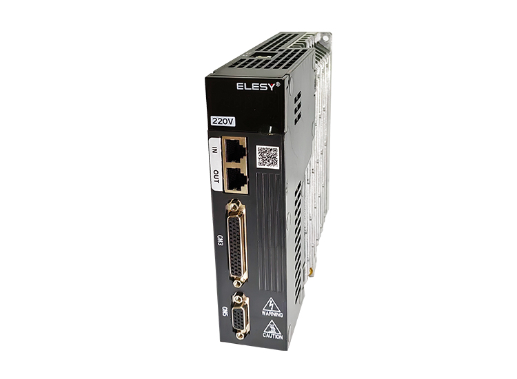
ES1-5R5S
Servo Driver|
ES1 Series Model |
5R5S | |||
| Rated Current Output | 5.5A | |||
| Power Supply | Single phase 220V/AC | |||
|
Type of cooling |
Natural air cooling | |||
| Mode of Main Loop Control | SVPWM control | |||
| Feedback Resistor | Built-in | |||
|
Operating Environment |
Temperature |
Working environment temperature:-10°℃~40°C(If ambient temperature ranges from40°C~50°C , please de-rate for use)(no frozing) Storage temperature:-20°C~85°C ( no frozing ) |
||
| Humidity | Less than90%,no condensation | |||
| Level of Protection | IP20 | |||
| Altitude | < 1000m(if the altitude is over 1000m,please de-rate for use) | |||
| Vibration | ≤0.6G ( 5.9m/s2 ) 10-60Hz discontinuous operation | |||
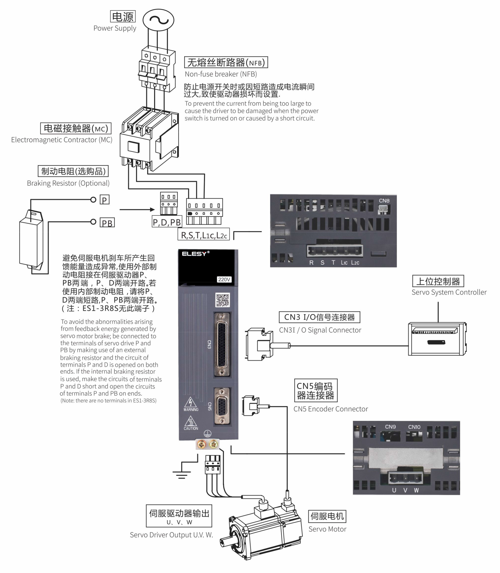
| Position Control Mode | Pulse Command Mode |
Pluse+symbol; Plase A+Plase B; CCW pulse+CW pulse |
||
| Max Output Pulse Frequency |
Pluse+symbol:500Kpps ccw pulse+Cw pulse:500Kpps Plase A+Plase B : single phase 50OKpps; Open collector transmission:200Kpps |
|||
| Command Smoothing Mode | External pulse control / internal position control (PR mode) | |||
| Command Smoothing Mode | Low pass and curve smoothing filtering | |||
| Electronic Gear Ratio | Electronic gear ratio:N/M(N:1~2147483647/M:1~21474836470) | |||
| Torque-speed Limit | Parameter setting mode | |||
| Speed Control Mode | Analog Comm and Input | VoltageScope | -10V~+10V | |
| Resolution | 12-bit | |||
| Input Resistance | 1MΩ | |||
| Time Constant | 25us | |||
|
Scope of Speed Control |
1:600 | |||
| Command Conteol Mode | Exterral analog command control/intermal resister control | |||
| Command Smoothing Mode | Low pass and smoothing filtering;s curve smoothing filtering | |||
| Torque-speed Limit | Parameter setting mode or analog input | |||
| Bandwidth | MAX.1.2k Hz(closed loop) | |||
| Torque Control Mode | Analog Command Input | voltage Scope | -10V~+10v | |
| Resolution | 12-bit | |||
| Input Resistande | 1MΩ | |||
| Time Constant | 25us | |||
| Command Control Mode | Exterral analog command control/intermal resister control | |||
|
Command Smoothing Mode |
Low pass and smoothing filtering | |||
| Speed Limit | Parameter setting mode/analogy input | |||
| Digital | Input |
1、Servo enabled 2、Alarm Reset 3、Forward Limit Restrictions 4、Reverse Limit Restrictions 5、Pulse Command Suppression 6、Zero Speed 7、Deviation reset 8、External Torque- speed Limit 9、Control Mode switch 10、Gain Switching1 11、Gain Switching2 14、Internal Speed Selectl 15、Internal Speed Select2 17、Electronic Cam Toothing 20、Internal Torque- speed Select 21、Internal Torque-speed Select2 24、Electronic Gear Ratio Select1 25、Electronic Gear Ratio Select2 26、Speed Command DirectionSelec1 27、Speed Command Direction Select2 |
28、Speed Command Direction Reverse 29、Emergency Sto 32、Original-point Regression Initiate 33、Original-point Regression Reference Point 36、Start Signal for InternalPosition Running 37、Motor Pause 38、nternal Position Select0 39、Internal Position select1 40、Internal Position Select2 41、Internal Position Select3 42、Internal Position Select4 44、 Full-dosed Internal/External Encoder Switching 45、 Full-closed Internal /External Encode Error Reset 53、Forward Limit restrictions 54、Reverse Limit Restrictions 55、Event-triggered Command |
|
| Output |
1、Servo Ready 2、Alarm Output 3、Positioning Finish 4、Electromagnetic Braking 5、Speed Achieve 6、Torque Achieve 7、2ero- speed Signal 8、Original-point Regression Finish 9、orque-spee 10、Speed Limit 11、Alarm Output 12、Cam Speed Output |
13、 Internal Position CommandFinish |
||
| Protection Function | Input /output phase lossprotection, over-speed, over-current, over-voltage, under-voltage, over-heating,abnormal braking over-load, posi tion ultra-error, abnormal encoder, etc. | |||
| Communication Function |
RS-485/USB |
|||
|
Note: 1、 TN System: the neutral point is directly connected to the earth in the electric power system and the exposed metal parts will be connected to the earth via the protective grounding conductor. 2、 Single -phase three-wire electric power system is used for the single-phase power supply models. |
||||
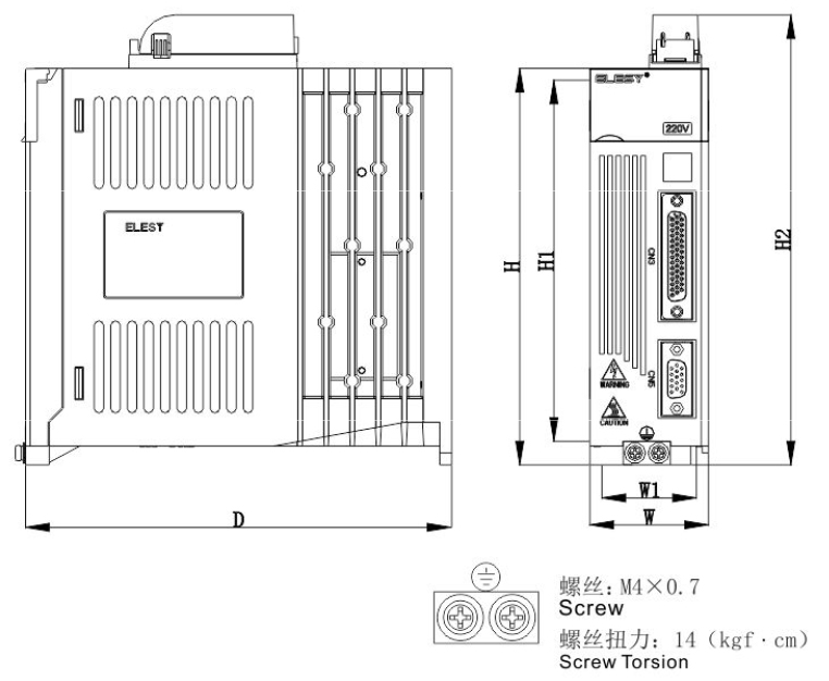
| Model | unit | W | H | D | W1 | H1 | H2 | SCREW |
| ES1-5R5S | mm | 41 | 160 | 180 | 29 | 161 | - | 2-M4 |


Wechat
QR Code
 Consult Now